If you've ever watched snow pile up on a roof and wondered whether the solar array underneath could actually hold that weight, you're asking the right question. Every winter, installers field calls from homeowners who notice sagging rails, loosened flashing, or panels sitting at odd angles after a heavy snowfall. In most cases, the problem traces back to one thing: the mounting system wasn't engineered for the snow loads the roof actually sees. Getting rooftop solar mounting design right for snow isn't a matter of over-building for safety's sake. It's a calculated engineering process that determines rail spacing, attachment point count, hardware selection, and even panel orientation.
This article breaks down how snow load shapes that process, what the codes require, and where designs commonly go wrong.
Why Snow Load Is a Structural Factor, Not an Afterthought
Snow doesn't just sit on a roof. It compresses, drifts, and redistributes itself in ways that concentrate weight unevenly across the surface. A flat blanket of snow might weigh 20 pounds per square foot, but drifting against a parapet wall, roof step, or the solar array itself can push localized loads to two or three times that figure.
Solar panels change how snow behaves on a roof in three ways:
They create a raised surface that snow can drift against, especially near the array's edges.
Standing seam metal roofs shed snow in sheets, which can slide directly onto lower array rows.
Racking rails interrupt natural snow sliding patterns, sometimes causing accumulation the original roof design never anticipated.
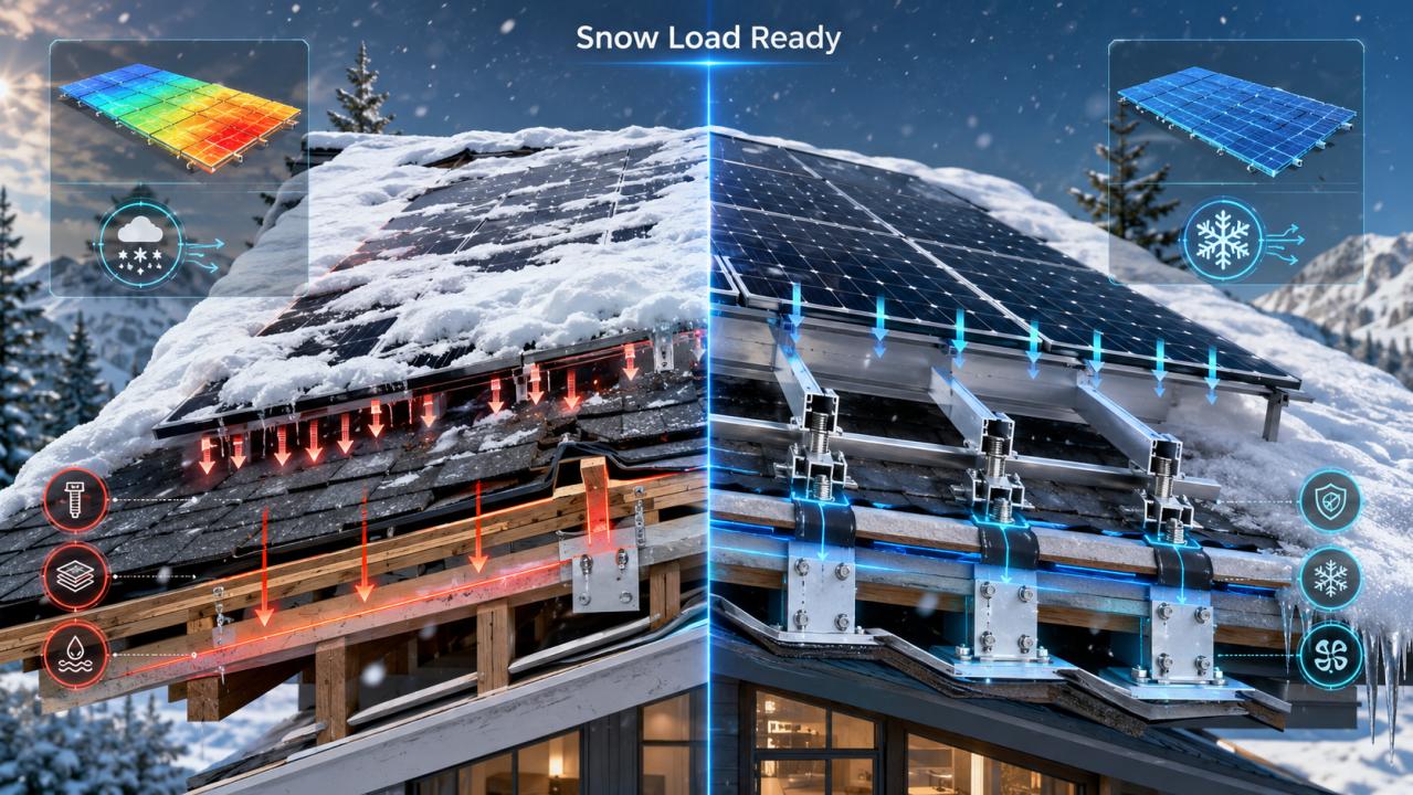
Because of this, mounting hardware has to carry both the distributed weight of the snowpack and the concentrated loads from drift and sliding. A rail system rated only for the roof's baseline design load, without accounting for these array-specific effects, is a common source of long-term structural stress.
Calculating Snow Load: Ground Load, Roof Load, and Regional Variation
Structural engineers start with the ground snow load figure published for a given jurisdiction, then apply a series of adjustment factors under ASCE 7 (the American Society of Civil Engineers' minimum design loads standard) to arrive at the actual roof snow load. Those factors account for roof slope, exposure to wind, thermal characteristics of the building, and the roof's importance category.
This is where geography matters enormously. A roof in Phoenix might see a ground snow load of zero, while a roof in International Falls, Minnesota, can face ground snow loads exceeding 70 pounds per square foot before any adjustment factors are applied. In regions like this, Roof-Tech solar mounting in Minnesota installations routinely factor in higher attachment density and reinforced flashing details specifically because the baseline snow numbers are so much higher than in milder climates. The same rail product installed in Georgia and in Minnesota may need entirely different attachment spacing to meet code in each location.
Engineers also distinguish between three related but separate figures: ground snow load, flat roof snow load, and sloped roof snow load. Each one feeds into the final structural calculation, and skipping straight from a regional average to a design decision without running the full adjustment sequence is a common source of undersized systems.
How Snow Load Drives Rail Spacing and Attachment Count
Once the design snow load is known, it directly determines two of the most consequential decisions in the mounting layout: how far apart the attachment points sit, and how many penetrations the roof needs.
Higher snow loads mean:
Shorter spans between rail attachments, since each attachment point carries a share of the total load, and closer spacing reduces the load per point.
More frequent structural attachments to rafters or trusses, which increases the number of roof penetrations that must be properly flashed.
Larger or reinforced mounting feet in some cases, to distribute concentrated point loads across a wider area of decking.
This is also where rail selection matters. A rail rated for a maximum span of 72 inches under moderate loads might need to drop to 48 inches or less once snow load calculations push past a certain threshold. Manufacturers publish span tables based on third-party testing, typically referencing ICC-ES evaluation reports such as AC428, which specify allowable spans under stated load combinations.
Snow Guards, Sliding Loads, and Panel-to-Panel Spacing
Snow load design isn't only about what falls on the array. It's also about what slides off it, and where.
On steep-slope roofs, especially metal roofing, accumulated snow can release suddenly and slide as a sheet. If the array sits below an unprotected section of roof, that sliding mass can strike the lower edge of the panels or the racking itself. Snow guards or fences upstream of the array are a common mitigation, breaking up the slide into smaller, more manageable releases rather than a single avalanche event.
Panel-to-panel and row-to-row spacing also plays a role. Tight spacing can trap snow and ice between rows, adding weight that wasn't part of the original distributed load calculation and creating a freeze-thaw cycle that stresses clamps and connectors over repeated seasons.
Common Mistakes in Snow-Load-Prone Installations
A few recurring issues show up across high-snow installations:
Using a single regional snow load figure for the whole project. Local terrain, elevation changes, and microclimates within the same county can significantly affect the applicable ground snow load.
Ignoring drift loading near roof-mounted obstructions. Chimneys, dormers, and adjacent roof planes create drift zones that require separate calculations, not a flat extension of the field load.
Treating rail span tables as guidelines rather than limits. Span tables are derived from tested load combinations. Exceeding the tested span under a higher-than-rated load voids the engineering basis for the installation.
Underestimating attachment pull-out resistance in older decking. Snow load isn't just about downward force. Wind uplift combined with snow weight changes the net load direction on fasteners, and older or thinner decking may not hold the same withdrawal resistance as new construction.
Conclusion
Snow load is one of the few structural forces that changes dramatically by location, and it has an outsized effect on how a rooftop solar mounting design comes together. From ground snow load figures and ASCE 7 adjustment factors down to rail span, attachment spacing, and snow guard placement, every layer of the design responds to how much weight the roof, and the array on top of it, will realistically bear each winter. Getting these calculations right at the design stage is what keeps a system performing reliably through decades of freeze-thaw cycles, rather than needing repair after the first heavy season.
Frequently Asked Questions
1. How much snow load can a typical solar roof mounting system handle?
It depends on the rail, hardware, span, and roof capacity. Systems are designed to a project-specific load from local codes, so hardware ratings vary by roof.
2. Does installing solar panels increase the snow load risk on a roof?
Solar panels weigh 2 to 4 pounds per square foot but affect snow drift and slide, requiring array-specific load calculations beyond the roof's baseline.
3. What building codes govern snow load for rooftop solar systems?
ASCE 7 provides minimum snow load calculations, referenced by the IBC and IRC, which most U.S. jurisdictions adopt for structural codes.
4. Do solar panels need to be removed before heavy snowfall?
Properly engineered systems are designed to support expected snow loads without needing panel removal, which isn't standard practice, as mounting design considers local snow conditions.