Quick Overview
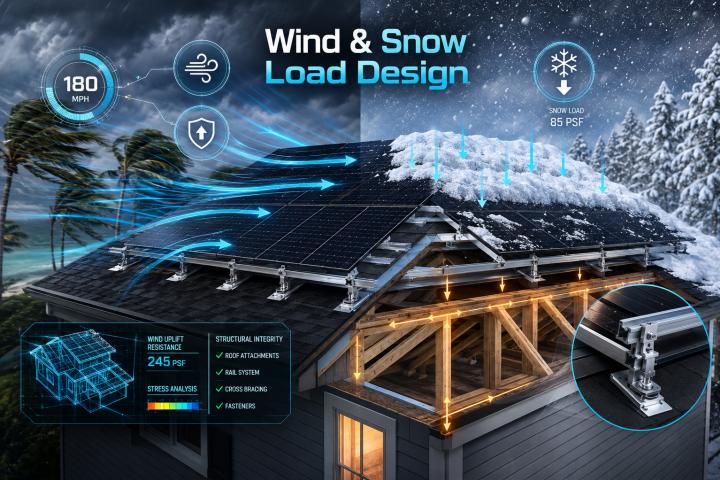
Wind uplift and snow accumulation are two of the largest structural forces a rooftop solar array has to survive, and they drive most of the engineering decisions behind racking layout
Racking manufacturers size rails, clamps, and attachment points using ASCE 7 wind and snow load calculations, not generic averages
Roof edge and corner zones carry disproportionately higher wind uplift pressure than the field of the array
Snow load design has to account for both accumulated weight and sliding or drifting snow against the upper rows of panels
Attachment spacing, not panel count, is usually the limiting factor in whether a racking layout passes engineering review
Why This Question Comes Up After the Storm, Not Before
A homeowner in Minnesota and a homeowner in coastal Florida are solving two different structural problems, even if they're buying the same solar panels. One system has to shed three feet of accumulated snow without the rails deflecting. The other has to resist wind trying to peel the array off the roof deck during a hurricane. Racking that works fine in one climate can be dangerously undersized in the other.
This is where a lot of confusion starts. A racking system rated for a project 200 miles away isn't automatically rated for a specific roof, because wind and snow load solar racking requirements change block by block depending on elevation, exposure category, and local ground snow load data. Understanding how these two forces actually load the structure explains why racking layouts that look similar on paper can require very different hardware underneath.
Wind Load: The Uplift Problem Nobody Sees Until It Fails
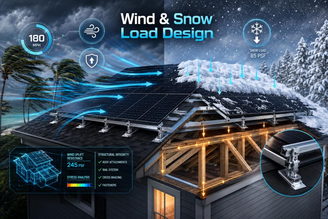
Wind doesn't just push against a solar array, it lifts it. As air moves across the panel surface, pressure differences form above and below the module, similar to what happens over an airplane wing. On a pitched roof, this uplift force concentrates most heavily at the corners and perimeter edges, an effect engineers refer to as zone loading.
ASCE 7 (the American Society of Civil Engineers' standard for minimum design loads) breaks a roof into zones, typically labeled Zone 1 through Zone 3, with corner and edge zones carrying uplift pressures that can run two to three times higher than the interior field. That's why racking layouts often call for tighter attachment spacing near roof edges even when the rest of the array uses standard spacing.
A few variables determine how severe that uplift pressure gets:
Basic wind speed: For the site, pulled from ASCE 7 wind maps and expressed in miles per hour
Exposure category: which reflects the surrounding terrain (open field vs. dense suburb vs. coastal exposure)
Roof height and pitch: Since taller buildings and steeper roofs generally see higher pressures
Building enclosure classification: which affects internal pressure coefficients
Third-party evaluation reports help installers compare how different racking products perform under these conditions. A published TriSMART Solar RT-MINI review, for example, documents uplift resistance data gathered during ICC-ES evaluation testing, giving engineers a reference point for attachment spacing on similar railless mounting layouts. Reviewing this kind of testing data matters more than trusting a manufacturer's marketing claims, because uplift capacity has to be verified under standardized test conditions, not estimated.
Snow Load: Weight, Drift, and the Sliding Problem
Snow load design starts with a simpler question than wind: how much does the accumulated snow weigh per square foot of roof? But the engineering gets complicated fast once drift and sliding enter the picture.
Ground snow load is the baseline figure, pulled from ASCE 7 maps or local building department data, expressed in pounds per square foot (psf). That number gets converted into a roof snow load using factors for roof slope, exposure, and thermal characteristics.
Two conditions complicate a straightforward flat calculation:
Drift loading happens when wind pushes snow against an obstruction, like a dormer, parapet, or the upper edge of a solar array itself, piling significantly more weight in a concentrated strip than the surrounding field carries. Racking installed near roof step-downs or adjacent to taller structures often needs reinforced attachment in exactly these drift zones.
Sliding snow is a different mechanism entirely. As snow on a metal or slick roof surface warms and begins to slide, it can pile against the downslope edge of an array, or against panels installed below an unracked portion of roof. This isn't a static weight problem, it's a dynamic load event, and it's one reason snow guards or strategic row spacing show up in racking plans for steep metal roofs in snow country.
Structural Load Path: Where the Force Actually Goes
Wind and snow loads don't stop at the panel. They travel through the racking rail, into the attachment hardware, through the roof decking, and ultimately into the building's structural framing. Engineers call this the load path, and every component in that chain has to be sized for the worst combination of forces it will see.
This is why attachment spacing, not module wattage or panel count, usually determines whether a design passes structural review. A layout with panels spaced at 48 inches on-center might need attachments every 32 inches in a high-wind zone, while the same layout in a low-wind interior region could use 64-inch spacing. UL 2703 testing establishes the mechanical load ratings for the racking and clamp hardware itself, but it's the site-specific ASCE 7 calculation that determines how those ratings get applied.
Common mistakes installers run into on this front include:
Using a single attachment spacing across the entire roof instead of tightening it at edge and corner zones
Sizing racking for the building's overall wind speed rating without adjusting for local exposure category
Overlooking drift loading near parapets, dormers, or adjacent rooflines
Assuming panel-rated wind resistance from the module datasheet substitutes for a racking-specific structural calculation
Conclusion
Wind and snow load solar racking design isn't a single calculation; it's a layered process that accounts for zone-based uplift pressure, ground snow load, drift accumulation, and the full structural load path from panel to framing. A racking system that performs well in one region can be structurally inadequate in another, which is why site-specific engineering, not generic manufacturer specs, determines what attachment spacing and hardware a given roof actually needs. Getting this right at the design stage is what keeps an array on the roof through the storm it was actually built to survive.
Frequently Asked Questions
What is the difference between wind load and snow load in solar racking design?
Wind load is the uplift and lateral pressure from moving air, concentrated at roof edges and corners. Snow load is the weight of accumulated snow plus drift and sliding forces. Racking must be engineered to resist both, often using different attachment strategies.
Do all solar racking systems need a site-specific structural calculation?
Most jurisdictions require a site-specific ASCE 7-based structural calculation for permits because wind speed, exposure, and snow load vary by location. A product rating isn't a substitute.
Why does attachment spacing change near the edge of the roof?
Roof edges and corners face higher wind uplift than interior areas, as per ASCE 7 zone loading. Tighter attachment spacing offsets this increased pressure.
Can a solar array fail from snow load even if it survives the winter's total snowfall?
Drift accumulation against obstructions or sliding snow can apply concentrated loads beyond typical snowfall, so racking near parapets, dormers, or roof step-downs often needs reinforced attachment points.